Cpu Ray Tracer
I apologise in advance for the “Art” in this post.
Ray Tracing is a rendering technique that more accurately simulates how light behaves in the real world than some of the more traditional approaches, such as rasterization.
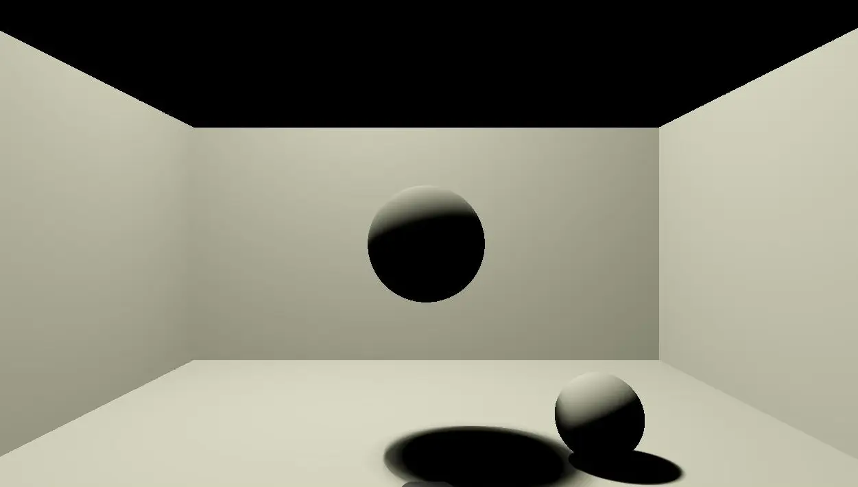
The lovely thing about Ray Tracing is it’s beautiful simplicity…
The not so lovely thing about it, is it’s time complexity.
What is a Ray?
For the purposes of Ray Tracing, a Ray can be defined by two vectors. One vector represents the ray origin, the other represents the ray’s direction. A ray moves in a straight line unless it is reflected or refracted by something.
The Algorithm
For every pixel on the screen, cast one or more rays. For each ray, find the first object in the scene it collides with. From the point of collision, create a new ray towards the primary light source. For this new ray, once again test for collision with all objects in the scene. If there are no collisions, then that light source is illuminating the pixel and we should see it. If however an object is blocking the path of the ray, it is in shadow.
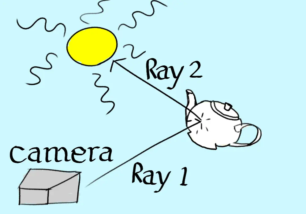
This is the simple version. It does not account for transparent objects, and will produce hard shadows. There are multiple approaches for how many rays to use, how they should interact with objects. In this post I will only focus on a very simplistic approach, which will prove challenging enough for our poor CPU.
Nvidia have a nice explainer series on youtube that goes into more detail on the different types of Ray Tracing.
The Problem
The observant reader might have noticed an issue with the algorithm presented above. Assume we have a monitor with 2 million pixels, and that we will cast 1 ray per pixel. Then assume we have a relatively small scene with only 100 objects, and a single large light source like the sun.
For each pixel, we will need to do 200 collision checks. For the entire scene, that is 400 million collision checks. Per Frame! For real time applications, rendering a single second of footage requires billions of calculations.
I should also point out that this is for a very simple case. It is common to use more than 1 ray per pixel to get a higher quality result. It’s also very likely you’ll have more than 1 light in the scene you need to test.
And it keeps getting worse…
Hard Shadows
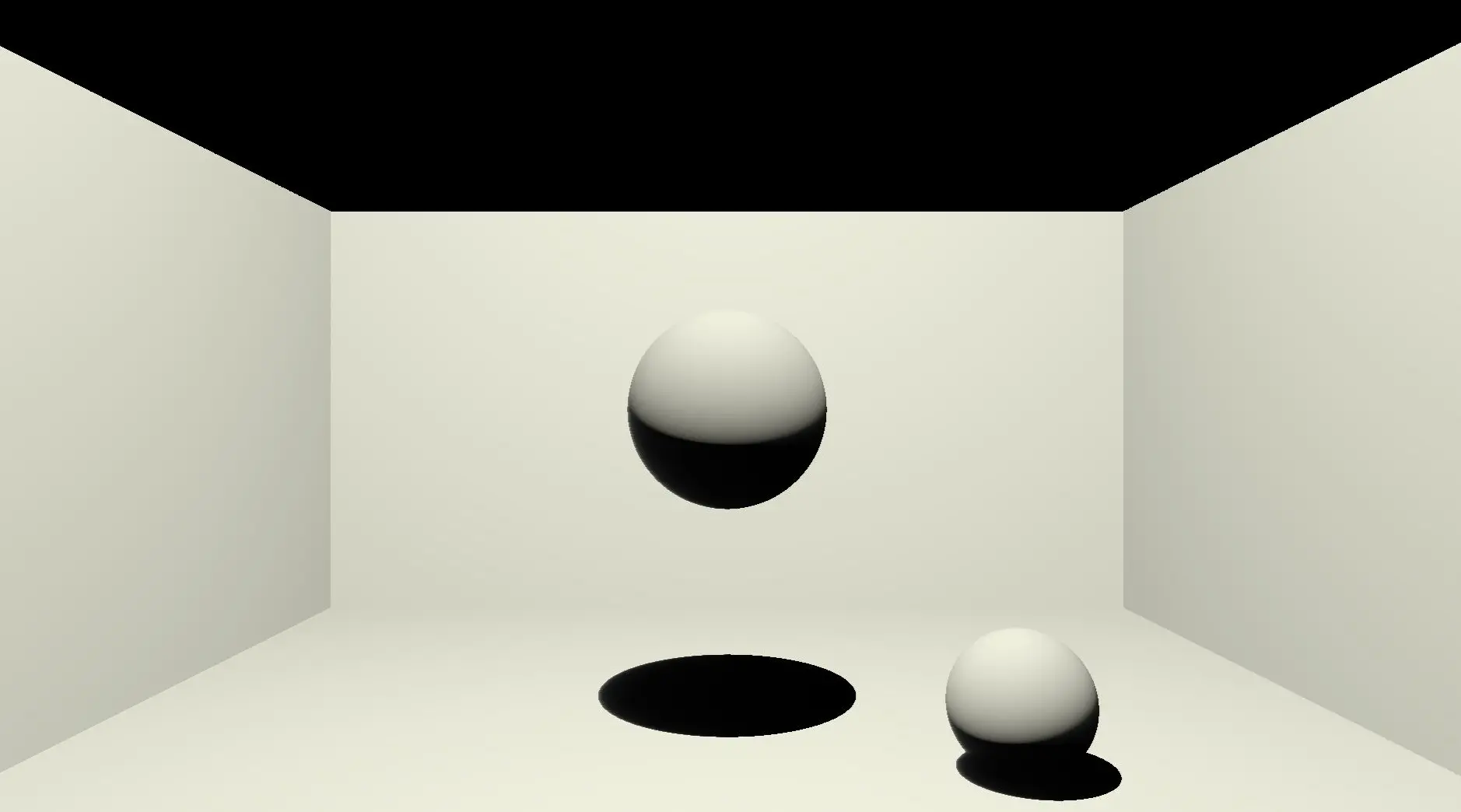 This is a render from my program demonstrating hard shadows in action. Notice how sharp the shadows on the ground plane are. This is a result of only casting one ray from a point of collision to a light source. The ray will either hit the light source or it won’t. This results in either total darkness, or full brightness.
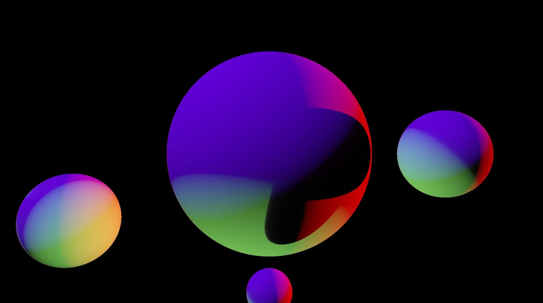 Here is a more colourful scene demonstrating the same issue. Here we have 3 light sources, each a different colour and 4 spheres. The centre sphere shows some hard shadows as light is being blocked by some of the spheres surrounding it.
Soft Shadows
The main issue here is we are ignoring that the light source will have a physical size. A pixel that has line of sight with the entire light source should be brighter than one which has it’s view partly blocked. A common way of achieving this is casting multiple rays towards different points on the light. If only half of them get there without colliding with something, then we know only half of the light is reaching us, so it should be half the maximum brightness.
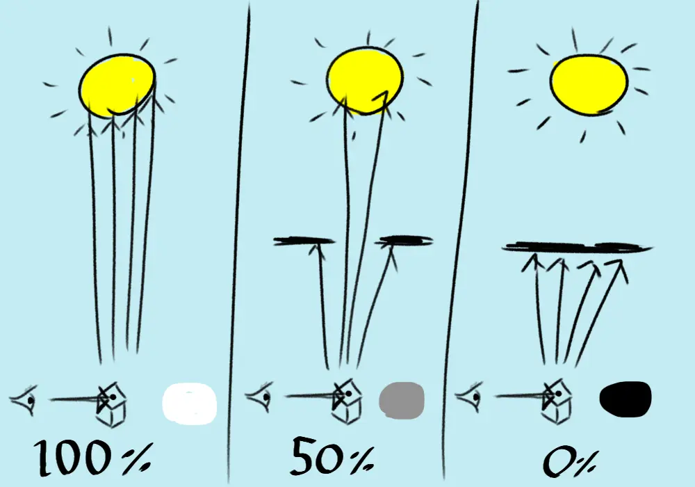 In this second piece of astounding art work, we are casting four rays from the collision point to the light source. In the middle example, half of the rays are blocked by objects either side. Casting a larger number of rays will give more accurate shadows but hurt performance.
Casting multiple rays like this will result in shadows with softer edges. My implementation actually has a bug regarding the distribution of points on the light source that I sample, but it works well enough to demonstrate the difference you get taking multiple samples.
 Here we can see the obviously softer edges. The difference would be even more noticeable with a large lightsource that was closer, and we’d need a lot of samples to get a nice image.
The more rays you cast, the more accurate your final image will be, but the longer it will take to render.
Improving performance
The Ray Tracing algorithm does have one saving grace as far as performance goes. It is trivial to parallelize. Since no pixel impacts how another pixel should look, we can assign different cpu cores to each calculate their own group of pixels.
In reality though, this is much better done on a GPU. I opted for a CPU ray tracer because I wasn’t interested in real time rendering, I simply wanted to play with the algorithm. I’ve setup OpenGL, Vulkan and DirectX before, and it’s often a lot of work. Indeed, the initial motivation to do this project came from the realisation one night that I could simply do it on the CPU. The cost of this however is that using a single core, each of the images in this post took over a minute to render.
The performance demands of Ray Tracing are so great that even graphics cards struggle with it. However, we are starting to see graphics cards with dedicated hardware to make real time Ray Tracing a possibility. AI is being used to reduce the number of Rays needed by filling in the blanks using a trained neural network. AI is also being used to upscale lower resolution images with negligable drop in quality. Some GPU’s now even have dedicated Ray Tracing cores to handle the huge number of collision checks required.
Traditional Optimisation
Reducing the number of collision checks is the primary goal. We can use many existing techniques from video games here. The major one is spatial partitioning algorithms. These make it possible for us to ignore scene objects far from the ray we are testing, and only worry about those nearby. It might help to think about a simpler problem from a top down prespective.
Consider a 2D game where the player is standing in a field with a bow. The player is surrounded by 100,000 goblins. If the player fires an arrow, we do not want to do a collision check against every goblin. Barring extreme wind, we can sensibly assume our arrow will never hit a goblin that is behind the player. Infact, because of the nature of arrow physics, the moment the arrow is released we know the rough area where a goblin could have an unfortunate encounter with it. So. We only want to test against Goblins in that area.
We have the same problem, we need to check every Goblin to see if they are in the area. May I introduce the humble Quad Tree to the rescue…
Quad Trees
Lets imagine our field of goblins as a tree. From the root node we immediately split our tree into four areas, top left, top right, bottom left, and bottom right. Note that we still need to do our expensive calculation once to do this, and also note the split into four, hence the name Quad Tree.
With 100,000 goblins, assuming an even distribution, we still have a lot of goblins in each node, so we then split our four areas again each into a further four. Now we have approximately 6250 Goblins in each node of our tree. So long as the Goblins don’t move, all we have to do is figure out which of the 16 areas our arrow will land in, that’s only 16 checks, and then check against all Goblins in that area. We’re down from 100,000 checks to just 6266.
We haven’t actually saved any performance yet, but as soon as we have 100 archers firing arrows at the same time, the benefits become obvious. Once we have our quad tree, we can compare 100 arrows against it. Even with a depth of only 2, that would be 626,600 checks. Yes that’s still too many which is why in reality you’d have a deeper quad tree, but it’s much less than the 10,000,000 checks you would have to do without the tree for those 100 arrows.
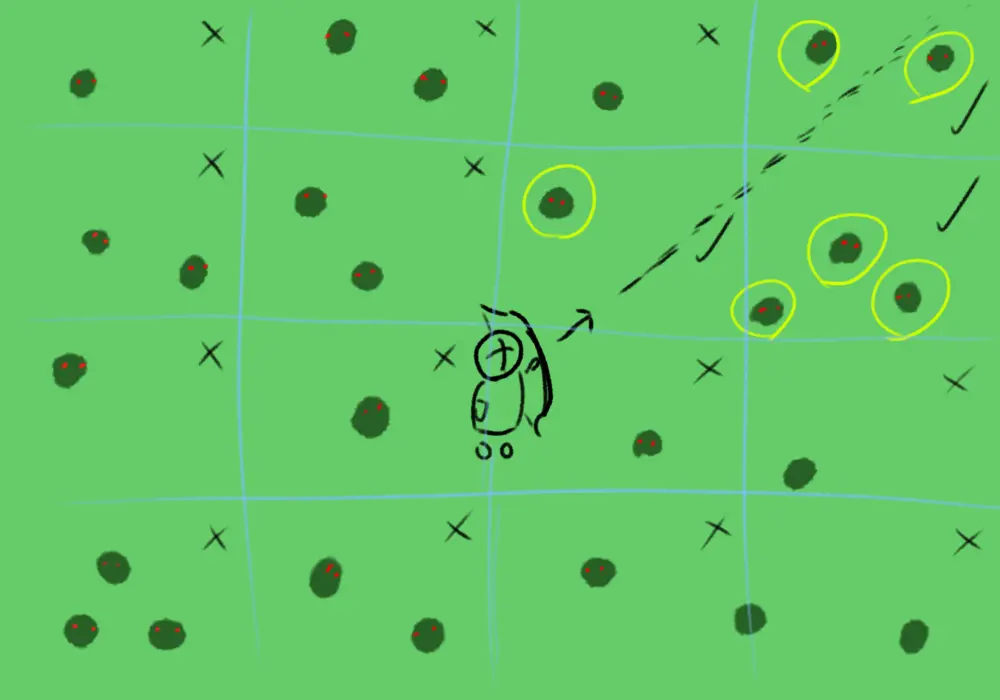 This carefully crafted image shows that our arrow will only pass through 3 nodes of the tree. We do not need to check the arrow against Goblins in any of the other nodes as we know they can’t be hit. If we know more about the arrows location, we may be able to narrow it down to a single grid square.
In ray tracing there is a similar technique we can use called “Bounding volume hierarchies”
Bounding volume hierarchies
This is a very similar idea to the Quad Tree. We build a tree to represent our scene geometry. We group nearby scene objects into volumes, typically Cuboids. When we come to do our ray tracing, we first test the Ray against a small number of large volumes. If the ray does not intersect the volume, there is no need to check all the smaller volumes or scene objects inside that large volume, so we have ruled out a huge number of checks.
Conclusion
Ray tracing is really fun to mess around with, and actually quite straightforward if done on the CPU. I’m hoping to have another go but on the GPU next time so I can play with more advanced ideas. I didn’t take material properties into account in my project, so I’d like to explore how the light from the light sources should interact with different material types. The simple model I present also doesn’t give you reflections which is something I’d like to try.
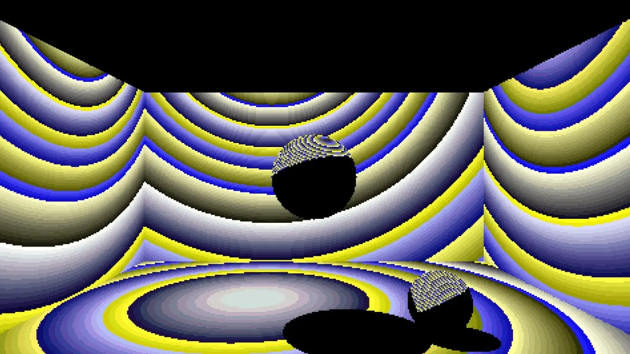
If you made it this far, congratulations. Here is a fun bug I had at one point during my project. Apparently, this is what happens when you use the Extended Reinhard tone mapper with too small a value for pure white…
